Hey, guys, in this video, we're going to talk about these really incredible tools that we use when solving a C circuits called phasers. All right, let's get to it now. A phaser is just a rotating vector. Okay? Phaser means phase vector. All the information contained by a phaser is contained in its X component. You can completely ignore the vertical components because it doesn't mean anything. Alright, Phasers air perfect for capturing all the information and representing it very easily for oscillating values like voltage and current, which we know oscillate. For instance, we know that the voltage is a function of time. Looks like some maximum voltage times cosine of omega T. This is exactly what I've drawn here. I've given one cycle off voltage that undergoes a Sinus soy. It'll, um, oscillation. Okay. And we wanna look at how a phaser can easily represent this exact information. Now, there are four times that I'm gonna be interested in. What I'll call time one when the voltage is at a maximum and positive time to when the voltage zero time three. When the voltages maximum, but negative and time. Four, when the voltage is back to zero Okay, So these four diagrams here Sorry, t two t three t four are going to contain the phaser that represents the information about the voltage at each of those four times. Thes diagrams, by the way, are called phaser diagrams for obvious reasons. Okay, Now, initially, the voltage is at a maximum. In order for a phaser to be at its maximum, it's entire length Has to be along the X axis. Okay, this is just because of vector that points along an axis. For instance, the X axis. That's when that vectors component is largest. Okay, the X component of the vectors largest when that vector points along the X axis. Now, the question is, which side left or right? Do we want to put it on by convention to the right is considered positive and to the left is considered negative. So I'm gonna draw the phaser like this. It's entirely along the X axis, which means that the voltages at the largest value it could possibly be because the phaser as it rotates. Remember, a phaser is a rotating vector is not going to change length. Okay, so this is our voltage phaser. That's a time one. Now, a time to the voltage is zero. That means that it has toe have no X component. So the phaser has toe lie entirely along the vertical access. The question is, is it up or is it down now, By convention, we consider phasers is rotating counterclockwise. Okay, so when it has zero x component at time to it is going to point upwards. By convention, we consider it as rotating counter clockwise. Okay, a time. Three. Now it has the maximum value again, but negative. So once again, since it's at a maximum, the phaser has a point entirely along the X axis. And since it's negative, it points to the left. Okay? And finally, at T 40 again. If it zero, it means it has no X component, which means it has to lie entirely on the vertical axis, since it was initially pointing to the left and it rotates counterclockwise. Now it's gonna point downwards, and this is the phaser. It's rotating counter clockwise, and it's rotating at the same angular frequency of the oscillations Omega. So it's just rotating at Omega. Okay, so if Omega is two per second, that means it does two full rotations every one second. Okay, Now, phasers are gonna be weird. When you guys first encounter them, it's gonna take practice to understand the phasers. So let's do an example to try to familiarize ourselves a little bit. Mawr with what a phaser is for the following phaser is sorry for the following voltage phaser. Is the voltage positive or negative? Remember, all the information is contained in the X axis. So all we care about is the X component, right? This which is about as long as this phaser is it's a little bit longer. Whatever. Since it's pointing to the right, we know that this is positive. Okay, it's projection is what we would call it. It's projection onto the X axis is positive. Okay, Now, the reason why phasers are used so much they're so useful and they're so great is that you can treat phasers at a particular instant in time. Remember that phasers are always rotating. So if you freeze time and take like a snapshot of it, you can treat phasers exactly like you would treat vectors. You can add them, you can subtract them, and you can find the magnitude of a phaser by using the Pythagorean theorem exactly like you would find the magnitude off a vector. So let's do an example illustrating that in the following phase diagram find the direction of the Net. Phaser for the three phases shown is the resulting quantity the phaser describes. Positive or negative. Let's say that these three phasers were of the same type. Let's say that they each described voltage. Alright, justus an example they could all describe current. For instance, What I need to do is describe this as an entire net voltage phaser. Okay, so we have to phasers pointing in the same direction. Sorry. Throughout the label these V one, V two and V three, V one and V three points along the same axis. Okay, so the net of those two is gonna point in the direction of the three because of the freeze. Longer right. It's like two forces that are pointing in opposite directions. The larger force winds, so we still have a phaser pointing in the direction of the three just a little bit smaller. Now V two is left alone because it's perpendicular. So here's V two. Here's V three, minus V one okay. I don't know which of these is longer V two or V three minus V one. But I know that our net phaser is gonna point somewhere in between here, right? Maybe it's in this direction. Maybe it's directly along the axis. Maybe it's down here. It actually doesn't matter because it's pointing to the right, no matter what, our value is always going to be positive. Sorry, I shouldn't say always. Our value is going to be positive. Regardless of where specifically, the Net phaser points. It's going to be positive. In order for the net phaser to result in a negative value, it would have had to point to the left. And it clearly does not point to the left. Okay, this is only the beginning with phasers. Guys, phasers are confusing. Just like vectors were confusing when you first saw them. But the more you use phasers, the more you become comfortable with them in future videos. We're going to talk about phasers in specific context of voltage and current in circuits, and it will become much more clear what they do and how to use them. All right, guys, Thanks for watching
2
Problem
Problem
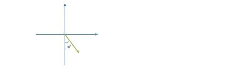
The following phasor diagram shows an arbitrary phasor during its first rotation. Assuming that it begins with an angle of 0° , if the phasor took 0.027 s to get to its current position, what is the angular frequency of the phasor?
A
0.141 s−1
B
19.4 s−1
C
38.8 s−1
D
194 s−1
3
example
Converting Between a Function and a Phasor
Video duration:
3m
Play a video:
Hey, guys, let's do a phaser example in this case, an example that deals with relating the phasers equation to the phaser diagram. Okay, the current in an a C circuit is given by this equation. Draw. The phase of that corresponds to this current at milliseconds, assuming the phaser begins at zero degrees. So in the beginning, the phaser is going to start here at zero degrees, and it's gonna rotate through some amount of angle to arrive at its final position. We want to figure out what that angle is, so we know where to draw the final position of this phaser. Remember that The angle is just gonna be omega. The angular frequency of the phaser times t. Okay, now we know that tea is just 15 milliseconds. So what's the angular frequency of the phaser? What? We're told that the angular frequency of the current is 3 77 and that's going to be the angular frequency of the phaser. However quickly it's oscillating on a function right. If I were to draw, this is an oscillating graph is gonna be the same rate as how quickly it's oscillating on the face of diagram. Those angular frequencies are the same. So this is just going to be 3 77 times milliseconds. Millions 10 to the negative three. And this equals 566 radiance. We want this to be in degrees because it's easiest to graph degrees for us or sorry to draw degrees on the diagram. Remember, you can convert by dividing this by pie and multiplying it by 180 degrees. This is gonna be 324 degrees. Okay. I'm gonna minimize myself and draw the space with diagram. Yeah, okay. It started from zero degrees. Don't forget, the phaser began at zero. Starting from zero and rotating counter clockwise. This phaser ends up in the fourth quadrant because 24 is greater than 2. 70 but less than 3. 60. Okay, there are two other ways that you can represent this number if you want. This one is 3 24. As the full rotation, you can represent it from the negative y axis if you want, and this would be 54 degrees. Or you can represent it from the positive X axis if you'd like. And this would be 36 degrees Either way, this is correct. But the important thing to remember is that this value 24 is how far it traveled from its initial position. It started at zero degrees, and phasers always rotate counterclockwise. So this is 324 degrees. All right, guys, Thanks for watching.
4
Problem
Problem
An AC source oscillates with an angular frequency of 120 s-1 . If the initial voltage phasor is shown in the following phasor diagram, draw the voltage phasor after 0.01 s. (Select the correct absolute angle below of the phasor's location below after you have drawn it.)
A
8.3×10⁻⁵ radians
B
1.2 radians
C
2π radians
D
15 radians
5
Problem
Problem
A phasor of length 4 begins at 0° . If it is rotating at ω = 250 s−1 , what is the value of the phasor after 0.007 s?